Phase cancellation to eliminate interference
by Fred W Daniel
Phase
cancellation can be used to eliminate on-channel noise and
interference, that is impossible any other way. It can also be used to
reduce or eliminate noise or receiver overload, caused by a nearby
transmitter, that notch filters are ineffective in controlling. There
are many repeater sites that are common to high-power FM and TV
broadcasters. Because of this close proximity, enormous amounts of
broadband noise is created by the high-power transmitters, that
radiates beyond the assigned frequency of the broadcaster. This is
common to all transmitters, but when the transmitter operates at 5,000
or 50,000 watts, off-channel noise can be as high as 1 to 10
milliwatts. This does not seem like much, but because this noise source
is very close to you, it can impair your receiver because it is
broadband and actually on your channel.
 In the Los Angeles area,
Mt. Wilson is where many FM stations and almost all TV stations are
located. This site for years has been difficult, at best, to
operate a repeater from. With the proper selection of antennas, and
other hardware, a near perfect receiver can operate, with the aid of
phase cancellation. This technique cannot solve impossible problems,
where more than 50 dB of noise reduction is required. However, this
technique has been used for decades by cable TV head-ends, to eliminate
interference from co-channel TV stations. Microwave Filter Co. has build the model 2903 for many years for the cable industry, but hardly anyone in the Land Mobile market is familiar with this technique.
In the Los Angeles area,
Mt. Wilson is where many FM stations and almost all TV stations are
located. This site for years has been difficult, at best, to
operate a repeater from. With the proper selection of antennas, and
other hardware, a near perfect receiver can operate, with the aid of
phase cancellation. This technique cannot solve impossible problems,
where more than 50 dB of noise reduction is required. However, this
technique has been used for decades by cable TV head-ends, to eliminate
interference from co-channel TV stations. Microwave Filter Co. has build the model 2903 for many years for the cable industry, but hardly anyone in the Land Mobile market is familiar with this technique.
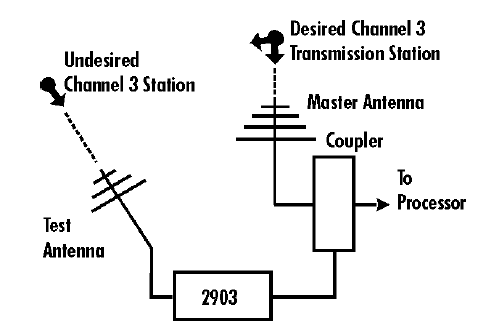
There are some issues to remember, while designing, testing, and maintaining phase cancellation systems.
-
Being able to directly sample a small signal from the offending
transmitter is more reliable than off-the-air sampling of the signal.
The null can be 10 to 20 dB deeper, and can be maintained longer,
without alignment.
- Matching the phase angle is not as critical as
the matching the amplitude. For a notch of more than 25 dB, the
amplitude must be within 0.1 dB, so stable components are a necessity.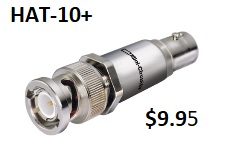
- The null is fairly broadband, but there is several dB roll-off, on either side of the center frequency, for several MHz.
-
For alignment, an older analog spectrum analyzer may work better than a
new $50,000 digital spectrum analyzer. The new digital analyzers don't
show noise very well.
Be sure to test, and learn, on your
bench FIRST. Use one or two signal generators and a analog FM receiver, with
some cables, an variable attenuator, line stretcher, and spectrum
analyzer. RF carriers are easy to learn with, but noise is a bit harder
to see on a receiver or spectrum analyzer, and maintain alignment.
 In
the Los Angeles area, there are many repeaters on T-Band channels 14
and 21. A few years ago, a Tijuana, Mexico channel 21 TV station went
on the air, about 78 miles from the nearest LA channel 21 repeater.
This killed most channel 21 repeaters on hilltop sites, as the HDTV
signal was almost 6 MHz wide, and covered all of the repeater receive
band. Many repeater sites eventually installed phase cancellation
systems
to reduce the impact, We simply used a 8 element beam as the sample
antenna, and coupled it into our main receive antenna with a small
variable attenuator. We did not have a line stretcher at the time, so
we used a variety of coax lengths to get the phase in the general
range. We were forced to use about 6 right angle adapters in series to
get the phase just right. We got a reasonably stable 32 dB rejection.
That saved us a second trip to the mountain. Eventually,
the Mexican station moved to another channel and we removed all the
excess hardware.
In
the Los Angeles area, there are many repeaters on T-Band channels 14
and 21. A few years ago, a Tijuana, Mexico channel 21 TV station went
on the air, about 78 miles from the nearest LA channel 21 repeater.
This killed most channel 21 repeaters on hilltop sites, as the HDTV
signal was almost 6 MHz wide, and covered all of the repeater receive
band. Many repeater sites eventually installed phase cancellation
systems
to reduce the impact, We simply used a 8 element beam as the sample
antenna, and coupled it into our main receive antenna with a small
variable attenuator. We did not have a line stretcher at the time, so
we used a variety of coax lengths to get the phase in the general
range. We were forced to use about 6 right angle adapters in series to
get the phase just right. We got a reasonably stable 32 dB rejection.
That saved us a second trip to the mountain. Eventually,
the Mexican station moved to another channel and we removed all the
excess hardware. 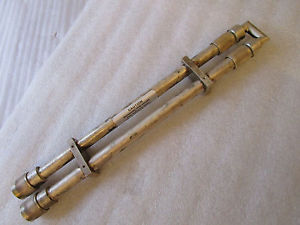
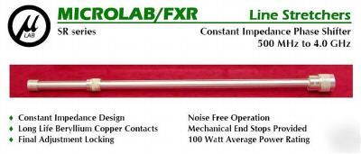
To get started, you will
need something to vary the phase of the null signal at least 180
degrees. The preferred device is called a "line stretcher," that is
nothing more than a 50 ohm piece of transmission line that you can vary
the length of. See photos for examples. Depending upon the
frequency, other passive devices will work, provided the
amplitude does not change while adjusting the phase. If you have
a phase shifter that
will not shift 180 degrees at your frequency, then you can create
short Male-Female coax jumpers that are 1/4, 1/2 and 3/4
wavelength, with the
cable velocity factor calculated into the length. For example, a
half-wavelength at 460 MHz. is about 12 inches. If you are using
RG-213/U, the Velocity Factor [VF] is 0.66 so you would multiply the
length by the VF, or 12 x 0.66 = 7.9 inches. The overall
measurement varies slightly, depending upon the connectors used. For
example, Type-N connectors add slightly more to the overall length than
UHF connectors like a PL-259, due to the air dialectric inside the
connector. Typically, UHF connectors work poorly above 150
MHz because the impedance is about 35 Ohms, instead of 50 Ohms.
 Next,
you will need a variety of fixed attenuators such as 3-6-10-20-30 dB,
plus a 3 to 10 dB multi-turn variable attenuator, to be able to adjust
down to 0.1 dB. Examples are
Next,
you will need a variety of fixed attenuators such as 3-6-10-20-30 dB,
plus a 3 to 10 dB multi-turn variable attenuator, to be able to adjust
down to 0.1 dB. Examples are 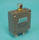 shown in nearby photos. Some technicians
prefer to use a expensive step/variable attenuator to test with, then
assemble the required attenuator with mostly fixed elements. Last you
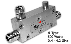
will need an assortment of 10, 15, and 20 dB couplers, to use to inject
the null into the receiver system, with the lowest main-line loss. Remember,
replacing the attenuators or any element could change the phase, due to
the length of the coax changing. Sometimes an amplifier is
necessary in the sample line to achieve a great enough signal to null
properly. Avoid using an amplifier if possible because it is hard
to maintain the gain within 0.1 dB, even with a regulated supply.
shown in nearby photos. Some technicians
prefer to use a expensive step/variable attenuator to test with, then
assemble the required attenuator with mostly fixed elements. Last you
will need an assortment of 10, 15, and 20 dB couplers, to use to inject
the null into the receiver system, with the lowest main-line loss. Remember,
replacing the attenuators or any element could change the phase, due to
the length of the coax changing. Sometimes an amplifier is
necessary in the sample line to achieve a great enough signal to null
properly. Avoid using an amplifier if possible because it is hard
to maintain the gain within 0.1 dB, even with a regulated supply.
Last,
you may experience difficulty measuring the level of noise affecting
your receiver. Sometimes it works best using the RSSI output on a
standard FM receiver. Other people finish off their testing using the
standard Motorola Desense Test setup with a IsoTee or coupler on the
test receiver and signal generator.
Off-Site Links of Similar interest [which may be copyrighted]:
50 MHz Receiver Noise Canceling Front-end
Phase Shift Cancellation of Unwanted VHF RF
Revised April 25, 2018