Duplexer
vs. Receiver combining -
by Fred Daniel
In
a perfect world, there would be no need for duplexers. Each repeater
would have a separate antenna for the receiver and transmitter, and
there would be no interaction between antennas. Since tower space is
usually both limited and expensive, this is not practical. From this
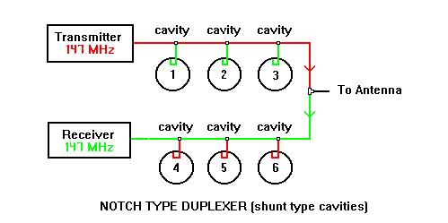
was born the duplexer. There are two basic types of duplexer. The
band-pass and the notch models, and some designs combine both
features. Some economy is realized with a duplexer since the repeater
only requires one antenna and feedline. This is ideal at a site with only one or two repeaters.
The
least expensive is the notch duplexer, which simply notches the transmit frequency
from the receiver line and notches the receive frequency from the
transmit line.
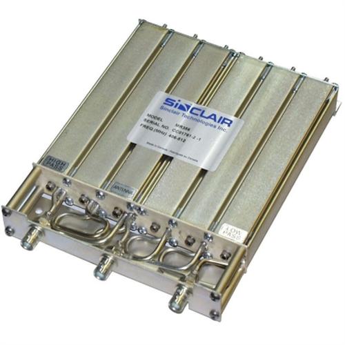 Typically, this model is small [see adjacient photo], with
low insertion loss, and the isolation is typically 70 or 80 dB. In
some cases, you may require additional filtering or a notch
duplexer
with 100 dB isolation for proper operation. The
notch frequencies are very narrow and must be retuned,
whenever a different frequency is desired, even 50 KHz away.
Typically, this model is small [see adjacient photo], with
low insertion loss, and the isolation is typically 70 or 80 dB. In
some cases, you may require additional filtering or a notch
duplexer
with 100 dB isolation for proper operation. The
notch frequencies are very narrow and must be retuned,
whenever a different frequency is desired, even 50 KHz away.
 The
band-pass duplexer is somewhat more robust in design, It is usually
larger in size, has a little more insertion loss as compared to a
notch duplexer, and almost always has at least 100 dB of isolation.
The operating frequencies are less critical and vibration is less of
an issue in regard to tuning. This is the preferred design when
expense is not an issue. In addition, it is not unusual to see 2 to 5 adjacent
channels on a hybrid transmitter combiner being duplexed within 75
KHz, provided the overall power specification is not exceeded.
The
band-pass duplexer is somewhat more robust in design, It is usually
larger in size, has a little more insertion loss as compared to a
notch duplexer, and almost always has at least 100 dB of isolation.
The operating frequencies are less critical and vibration is less of
an issue in regard to tuning. This is the preferred design when
expense is not an issue. In addition, it is not unusual to see 2 to 5 adjacent
channels on a hybrid transmitter combiner being duplexed within 75
KHz, provided the overall power specification is not exceeded.
 The
greatest value of a duplexer comes at sites with very few repeaters,
so the initial expense and added maintenance of using a receiver
combining system, is not normally justified. However, the gold
standard of performance is with properly designed and maintained
receiver and transmitter combining systems. However, since receiver
combining creates a single point of failure, steps must be taken to
insure survival, and as we proceed more will be presented on the
subject.
The
greatest value of a duplexer comes at sites with very few repeaters,
so the initial expense and added maintenance of using a receiver
combining system, is not normally justified. However, the gold
standard of performance is with properly designed and maintained
receiver and transmitter combining systems. However, since receiver
combining creates a single point of failure, steps must be taken to
insure survival, and as we proceed more will be presented on the
subject.
 Proper
receiver combining simply means tailoring and grooming every signal
that reaches your receivers, whether you have 5 or 100 in your
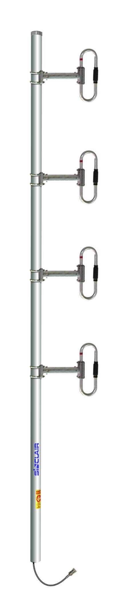
system. It is common to use a wideband antenna such as the Sinclair 4
dipole as your main receive antenna. These will easily tune 420 to 470
MHz with 9 dB offset gain.
Proper
receiver combining simply means tailoring and grooming every signal
that reaches your receivers, whether you have 5 or 100 in your
system. It is common to use a wideband antenna such as the Sinclair 4
dipole as your main receive antenna. These will easily tune 420 to 470
MHz with 9 dB offset gain.
In your initial design, you must decide what separate bands
of frequencies can be combined in each system. For example, it may be
simpler to filter 455-459 MHz. and filter 466-470 MHz. seperately, then re-combine to distribute.
With
receiver multi-coupling, the pre-selector is the first filter encountered, by the main antenna and
brought to the equipment building by the feedline. The pre-selector
is usually found to be one or more "window" filters. In some cases, notch cavities are
added to the pre-selector, to reduce the bleed-through of a local
transmitter operating near the window band-pass frequency. When
building a pre-selector, large high-Q cavities are not required. A
series of small low-Q cavities work better to create a low-loss
window, with provides very steep attenuation on the sides. If the desired
window needs to be wide or operate at VHF frequencies, a series of
helical resonators are usually preferred, due to size issues. At UHF
frequencies and above, inter-digital filters are often used. The
ideal pre-selector loss is zero, but the target is usually less than
2 dB. Keep in mind, any loss from feedline or the pre-selector,
before the first amplifier, cannot be made up in gain from the
amplifier. That is why on tall towers, and other critical
applications, the pre-selector and first amplifier is placed close to
the antenna, at the top of the tower. More on this later. A thorough
discussion of the various filter designs are beyond the scope of this
discussion, but can be found elsewhere on this web site.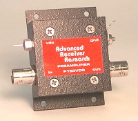
The
first or only amplifier (amp) in a distribution systems must have low
internal noise and a high-intercept rating. The noise figure in dB
will add to the feedline and pre-selector losses to reduce the
level of weak receive signals. The intercept point is a threshold
measurement, of the TOTAL level of all signals entering the amplifier
before internal mixing occurs. This mixing should be avoided at all
cost, as this will create interference from an effect called
intermodulation, or intermod for short. Receiver pre-amps used in
most radios, or built for external amateur radio use, typically have a low
intercept point. That is why connecting receivers or transceivers
directly to an antenna, will cause intermod to occur at locations
with as few as 3 other repeaters. This intermod will not only appear
in the "barefoot" receiver, but will also cause
interference in other receivers at the same site, even receivers
served by a quality multi-coupling system. The reason is because the
intermod creates signals on the same frequency you desire to receive,
and transmits them on the companion receive antenna, so it is not
practical to filter. The most preferred amplifiers available are made
by www.AngleLinear.com or www.advancedreceiver.com on the web.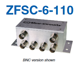
Signal
splitters are the preferred device to divide the output of the
amplifier, for distribution to the various receivers. These are
similar to cable TV splitters, but are of a better quality and are 50
ohm, instead of 75 ohm. They are available in splits of 2 and up to 24
and have a typical insertion loss [beyond the power split] of less
than 1 dB. The MiniCircuits.com ZFSC-6-110 shown is an ideal
splitter.
In most cases, the typical amplifier has enough gain to drive up to 36 receivers, with several dB of
surplus gain to compensate for cable losses from the distribution
panel to the individual receivers. When your design worksheet
indicates you will have surplus gain, beyond zero dB, a simple inline
attenuator should be inserted on the OUTPUT of the amplifier, to
reduce the gain. Any surplus gain beyond several dB will reduce the
3rd-order intercept point of your receiver and bring you closer to
the point where that receiver will create internal intermod.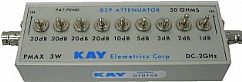 However,
if you use a calibrated step attenuator such as a Kay model 839, in
front of the receiver, you will notice several DB of additional gain
does yield a noticeable improvement [using SINAD measurement]..
However, you will reach a point where additional gain no longer shows
an improvement. Again, I will stress the need for double-shielded
silver-plated cable such as RG-400, with silver-plated crimp
connectors in your receiver distribution system. Ordinary coax cables
such as RG-58/AU appear to work good, but only have a little over 60%
shield coverage. This will allow local transmitter signals to enter
the distribution system cabling and add to the overall RF energy
appearing at each receiver, thereby reducing the point where overload
can occur. This warning also applies to the connectors used. Quality
silver-plated crimp connectors such as Kings or Amphenol are
essential, as tin-plated connectors with poor plating [parts from
China] will allow external RF to enter the distribution system. If
you have done your installation correctly, you should be able to
remove the main receive antenna and terminate the pre-selector input
with a 50 ohm load, and not receive a on-channel hand-held in the
same room. This is a tough test, but controlling what enters your
receiver distribution system is the objective.
However,
if you use a calibrated step attenuator such as a Kay model 839, in
front of the receiver, you will notice several DB of additional gain
does yield a noticeable improvement [using SINAD measurement]..
However, you will reach a point where additional gain no longer shows
an improvement. Again, I will stress the need for double-shielded
silver-plated cable such as RG-400, with silver-plated crimp
connectors in your receiver distribution system. Ordinary coax cables
such as RG-58/AU appear to work good, but only have a little over 60%
shield coverage. This will allow local transmitter signals to enter
the distribution system cabling and add to the overall RF energy
appearing at each receiver, thereby reducing the point where overload
can occur. This warning also applies to the connectors used. Quality
silver-plated crimp connectors such as Kings or Amphenol are
essential, as tin-plated connectors with poor plating [parts from
China] will allow external RF to enter the distribution system. If
you have done your installation correctly, you should be able to
remove the main receive antenna and terminate the pre-selector input
with a 50 ohm load, and not receive a on-channel hand-held in the
same room. This is a tough test, but controlling what enters your
receiver distribution system is the objective.
 In
order to make system testing easier, it is suggested that a
non-directional 30 dB coupler be inserted between the main receive
antenna and the pre-selector. This will allow a technician, without
disturbing the main receive antenna for the site, to:
In
order to make system testing easier, it is suggested that a
non-directional 30 dB coupler be inserted between the main receive
antenna and the pre-selector. This will allow a technician, without
disturbing the main receive antenna for the site, to:
1) inject a
signal for testing the system or,
2) testing a specific receiver, or
3) connect a spectrum analyzer to see what is coming down your main
receive antenna.
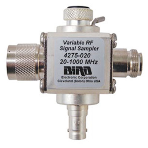
By using a 40 dB coupler, the calibration on the
signal generator is off by a factor of 1,000, thereby representing 1
microvolt as 1 millivolt, and 10 microvolt as 10 mill volts. This
reduces the confusion found when using a 20 dB coupler. The use of a
non-directional coupler such as the Bird model 4275-020 is desirable so
that the coupling of 30 dB remains uniform for both signal injecting
and monitoring what is coming down the main receive feedline. If the
location of the coupler is some distance from the receivers at the
site, you can use a 20 dB coupler and extend the coupled port across
the building using RG-214 or Heliax, then inserting an inline
attenuator of the appropriate value to compensate for the extension
cable losses. This will insure you remain coupled at 30 dB for ease
of calibration.
We
can now discuss the issue of single-point-of-failure introduced
above. At the very least, the person charged with the maintenance of
a receiver distribution system should carry on-hand either at the
site or in the service vehicle, a complete set of all replacement
amplifiers and splitters. This is in case you take a bad lightning
strike. Spare filters are rarely required, as all inputs and outputs
are simple wire loops to ground. However, spare pass and notch
cavities are handy to have at the shop to experiment with, and used
to train technicians as to the proper tuning methods. Some
commercial tower top pre-selector/amplifier designs, claim increase
reliability by using two amplifiers, phased in parallel. This is a
good idea, as the output will only drop 3 dB should one amplifier
fail. The pair of amplifiers can be monitored by constantly measuring
the current that powers the assembly going up the output coax, from
the equipment building. If funds are available, a better solution
might be a second primary receive antenna, with its own pre-selector,
and amplifier. a remotely controlled coax relay could switch the
splitter system between the two systems, should a need arise. A few
repeaters are built with dual diversity receivers, so the second
antenna system could also feed that. I have seen repeaters equipped
with a JPS Communications SNV-12 voting system, where both receivers
are at the
same site, on different antenna systems at least several wavelengths
apart. The objective was to
eliminate flutter and picket-fence effects on the repeater input. It
worked very well for that.
Some
ideas for remotely performance testing the receiver distribution
system, or any repeater, range from the simple to the sophisticated.
The simplest approach is install a beam antenna at your shop, fed
with Heliax cable to assure consistent and repeatable test result,
over time. Simply use your service monitor signal generator, with one
or two amplifiers, to provide just enough signal to perform a 20 dB
quieting or SINAD test. By recording the results, even long-term
changes can be revealed. If a quality signal generator or service
monitor is not available, then a small control station can be used,
with a 10 watt 20 dB attenuator, together with a step attenuator like
a Kay model 839, will work fine.
Continuous
on-site monitoring is easily achieved by selecting a unused
frequency, within the band pass of your receiver distribution system
pre-selector, and then transmit a very low power signal, just enough
the meet the SINAD test, on a companion receiver. It is important the
only way the receiver can hear the low-powered transmitter, is
through the receiver distribution system. So proper shielding of all
components is necessary. For example, a simple 1/2 watt exciter and
receiver is available for $16 from www.NiceRF.com as the model SA818-V
for VHF or the SA828-U for UHF bands. These can be fully shielded
using Bud aluminum
boxe. The power and other control leads must be RF
bypassed using bypass feed-through caps. You want the radios to be
very narrow-band, since the only modulation will be a single CTCSS
tone [i.e.: 151.4 Hz at 1 KHz. deviation], so that loss of your test
signal can be easily detected. Use attenuators to reduce the exciter
output to the minimum required signal level required. The frequency
might be the split between regular channels or a guard channel
between licensed services. Remember, the output will only be enough
to reach you primary receive antenna, and may not even be heard on
the ground below the tower. Once placed in service, you can connect
the receiver output to your alarm panel, or some other alarm facility
you have, to alert service personnel. If space or budget is limited
for the transmit antenna, an alternative is to couple the signal to
another existing transmit antenna, at the site. The same 30 dB
coupler described above will work fine, and will not cause any
mixing.